OFFSHORE SOLUTIONS FOR WIND TURBINE SUPPORTING STRUCTURES
|
|
|
- Kelley Heath
- 6 years ago
- Views:
Transcription


1 OFFSHORE SOLUTIONS FOR WIND TURBINE SUPPORTING STRUCTURES Author: Prof. Ing. F.G. Cesari/D. Mostacci Organization: Industrial Engineering Dpt., Bologna University

2 REFERENCE ELEVATIONS We have to consider two different elevations hub height or rotor axis elevation, which is the central point of the rotor surface and is the reference for all the wind actions on the turbine; interface level or interface between tower and substructure at which elevation could be situated the main platform, the connection tower-substructure and tower access. It is the separation between the turbine manufacturer s responsibility and that of the support structure designer in both a physical and an organisational sense. Wind turbine front view and lateral view 2
3 FORCES, MOMENTS, DISPLACEMENTS, ROTATIONS: DIRECTIONS 3
4 STRUCTURAL ANALYSIS & VERIFICATIONS During the calculation steps of the structural analysis in support to the design have to be verified also theese following conditions In service analysis; Dynamic modal response and fatigue analysis; Seismic analysis; Load out analysis of the structure on barges; Lift analysis at dock-yard and on site; Barge transportation analysis; On-bottom analysis; Free floating and upending analysis during the installation phases in the sea; Foundation pile driveability analysis. 4


5 FUNCTIONS OF SUPPORT STRUCTURE The functions of the structural bodies are to support the turbine; to hold up all the loads from normal/extreme conditions, meteorology/sea regimes, the turbine operation and to transfer them to the seabed; to respect the stiffness degree requested by dynamic regimes of the turbine; to hold a minimal surface of the seabed; to have the tower entrance over the maximum wave level in every moment; to reduce/annul its maintenance during the plant life. 5


6 MAIN COMPONENTS OF WIND TURBINE SUPPORT SYSTEM Starting from the upper part the support structure consists of the tower usually made of two/three sections riveted each other supporting at the top the nacelle with rotor; of the substructure connecting the tower base with own root; of the foundation in strict contact with soil and able to transfer to it all the loads coming from the top for the solution in touch with seabed ; of anchoring elements in connection with dead mass on the seabed, acting as foundation for floating solution. 6


7 OFFSHORE SUBSTRUCTURES: ALTERNATIVES AND SOLUTIONS Foundations in direct contact with seabed - monopile/monopod substructure; - tripod substructure; - jacket substructure; - gravity substructure); Foundations not in direct contact with seabed - floating substructure. 7

, upper terminal with")


8 CHARACTERISTICS OF SUBSTRUCTURE SOLUTIONS To describe a substructure type we have to consider these essential elements Substructure solution Main components Monopile/monopode portion inserted in the seabed, transition piece (TP), upper terminal with main platform; Tripode/Tripile Jacket skirt pipes with foundation piles, central element supporting the platform, beams/tubes connecting central element with skirt pipes foundation piles, legs, beams/tubes connecting legs together, platform at terminal part or deck; Gravity mass preparation of seabed to host body and the anti-scour defense, basement, neck connecting base with the head equipped by the platform. 8


9 MAIN COMPONENTS In the substructure a certain number of parts have to correspond to specific functions of the wind turbine operation, as in particular 1. boat landing structure; 2. main/service platform; 3. starways, small secondary platforms, loading areas; 4. J-tube to guide electrical cables; 5. cathodic protections. 9


10 BOAT LANDING The boatlanding is the structure to which a vessel can moor to transfer personnel and equipment to the substructure. The boatlanding consists of two mainly vertical fenders connected by stubs to the main structure. Depending on the environmental conditions and on the maintenance strategy of the operator, there may be one or more boatlandings connected to a support structure. 10


11 PLATFORMS & MAIN PLATFORM Platforms are intended as safe working areas for personnel that need to work on the structure Different functions can be identified; there are access platforms, resting platforms, and depending on the type of structures service platforms and airtight platforms. Resting platforms are required for safety reasons, when the vertical distance from the initial access point along a ladder to the next safe point exceeds a certain value. Service platforms are included for instance in the transition piece to facilitate the tightening of bolts at the base of the tower. 11


12 J-TUBES FOR ELECTRICAL CABLES To protect and guide the export cable into the support structure, a J-tube is installed on the structure. The name derives from the shape that the tube makes as it curves to a horizontal orientation near the seabed. J-tubes can be either internal, only to protrude from the substructure at the seabed level, or external. 12

13 LAY-OUT OF CATHODIC PROTECTION To provide cathodic protection against corrosion, blocks of particular alloys (aluminium base, etc.) may be installed as sacrificial anodes; Provisions must be made on the substructure to fix the anodes. 13
14 MONOPILE SUBSTRUCTURES In a synthetic representation of wind turbines supported by a monopile substructure in the world we have to consider the following plants Arklow Bank (7, 25, 2007, Ireland); Barrow (30, 90, 2005, UK); Blyth (2, 4, 2000, UK); Egmond aan Zee (36, 108, 2006, NL); EnBW Baltic 2 (39 turbines over 80, 288, 2013/5, DE); Greater Gabbard (140, 504, 2012, UK); Gunfleet Sands (48, 172, 2010, UK); Horns Rev 1&2 (80/91, 160/209, 2002/2009, DK); Kentish Flats ( , UK); Lely (4, 2, 1994, NL); London Array (340, 1224, 2014, UK); Lynn & Inner Dowsing (54, 194, 2008, UK); North Hoyle (30, 60, 2003, UK); Princess Amalia/Q7 (60, 120, NL, 2008); Rhyl Flats (25, 90, 2009, UK); Robin Rigg (60, 180, 2010, UK); Scroby Sands (30, 60, 2004, UK); Utgrunden (7, 10, 2000, SE); Walney 1 (51, 183, 2011, UK), in the round brackets the number of units, the total power, the year for beginning of electrical generation and the country. 14


15 MONOPILE SUBSTRUCTURE: CHARACTERISTICS Geometrical continuation of the tower ; Steel for all structural materials; Diameter range from 4 to 8 m (in function of turbine data and seabed height), thickness over 140 mm; Hydrodynamic loads increasing with outside diameter; Vertical loads transferred to the soil through the resistance of soil-tube and of the pile tip; Horizontal forces transferred to foundation through the bending moment; Stiffness improvement by increasing diameter and thickness with consequent difficulties in inserting the tube by pile-driver; Installation through driving or vibrating or seabed drilling; Transition Piece connected to monopile by grouting; Preparation of the area around the pile to avoid the strong effects of scour; Solution for seabed height range up to 30/35 m. 15

16 MONOPILE GENERAL ARRANGEMENT General arrangement of turbine on onopile (left) and transition piece (right) between foundation and tower during the mounting (in evidence J-tubes, landing structure, mean platform and in perspective the nacelle) 16


17 MONOPILE SUBSTRUCTURE Transition pieces (TP) ready to site transportation and complete of landing structure & main platform; Monopile equipped by cathodic defence, J-Tubes with the in/out submarine cables and anti-scouring area; Monopile in place with upper conical guide for the insertion of the TP. 17


18 MONOPILE SUBSTRUCTURE: SOME TECHNOLOGICAL ASPECTS Sheetes, whose edges are prepared as required for welding, are subjected to calandra, leaving with some small extension to test the longitudinal welding cords; The rings, aligned in a particular order to increase the general resistance, are automatically welded before a preliminary preheating; Tolerances on ovalization and eccentricity have to be respected costantly; To move the piece some device (like ear, bees or so on) have to be welded to each extremity; Openings have to be prepared in particular positions (for example, for J-Tube, if they are located inside the monopile). 18
; 48 Siemens turbines of 3.6 MW (SWT-3.")

19 GUNFLEET SANDS WINDFARM (GB) Gunfleet Sands windfarm at 7 km from Northern coast of Thames estuary on shallow waters (from -0.5 m to -10 m); 48 Siemens turbines of 3.6 MW (SWT ) supported by monopile substructures (5 m outside diameter, 40 m of inside lehgth in the soil); 172 MW total power with one SSE offshore; first electrical generation from 2010; distance: 435 m between two turbines of the same row and 839 m between adjacent rows; total sea surface of windfarm 15 kmq. 19
; Bard Offshore 1 (80, 400, 2013, DE), in round brackets the number of units, the total power, the year of beginning of electrical generation and the country.")
20 TRIPOD SUBSTRUCTURE In a synthetic representation of wind turbines supported by tripod/tripile substructure we have to consider the following plant Alpha Ventus (6 Multibrid turbines over 12, 60, 2010, DE); Bard Offshore 1 (80, 400, 2013, DE), in round brackets the number of units, the total power, the year of beginning of electrical generation and the country. 20

; Because of the need to drive piles, tripods not usable on a stony")
21 TRIPOD SUBSTRUCTURE: CHARACTERISTICS A three-legged steel frame which supports the main pile under water; Pinned to the seabed with three small piles, which have to be hammered; Diameter of piles smaller than the monopile; Suitable in a water depth of up to 30 metres or more; Good scour protection (another advantage of the tripod); Because of the need to drive piles, tripods not usable on a stony seabed. 21
 supporting the main platform;")


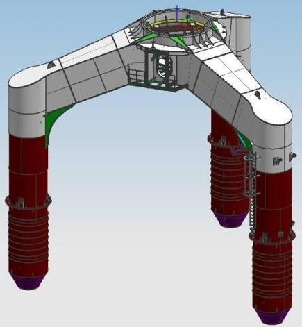
22 TRIPOD SUBSTRUCTURE: CHARACTERISTICS Three short legs directly connected to the central element (column or chandle) supporting the main platform; Foundation piles (Φ = 0,8-2,5 m) guided by the pile sleeves, which are the leg of the substructure; All the tructure in steel pipes (Φ = m) welded togheter; transition piece insert in the central column; structure less flexible than monopile thank the large base. Schemes of different configurations of tripod 22


23 ALPHA VENTUS TRIPOD: CONSTRUCTION The sheets wih edges bevelled are rolled and welded into large diameter tubular and conical sections for the main column, legs and lower braces. For the connections of the legs and braces to the main column and to the pile sleeves, the ends of these sections must be cut into the exact predefined shape and welded. A flange is fitted to the top of the main column. Several sections of the main column are lifted into alignment and welded together. Also the leg sections and the brace elements are assembled. Subsequently welds are ground and tested. The pile sleeves are preassembled and welded to the braces. When all elements have been tested and match specifications, they have assembled in the final arrangement of the structure. 23


24 TRIPILE SUBSTRUCTURE: CHARACTERISTICS Tripile consists of three steel piles which sit on a threelegged structure above the water level; Pinned to the seabed, as for the jacket and tripod; Tripile production relatively cost-effective due to its compact construction; First tripiles in operation in Bard Offshore I wind farm; According to the manufacturer, tripiles usable in a water depth of meters. 24


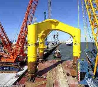
25 ALPHA VENTUS & BARD OFFSHORE I SUBSTRUCTURES 25
26 JACKET SUBSTRUCTURES In a synthetic representation of wind turbines supported by a jacket substructures we have to consider the following plants Alpha Ventus (6 REpower turbines over 12, 60, 2012, DE); Beatrice Windfarm (Moray Firth, 2, 10, 2007, UK); EnBW Baltic 2 (41 turbines over 80, 288, 2013/5, DE); Ormonde (30, 150, 2013, UK); Thornton Bank II (30, 185, 2013, BE) & III (18, 110, 2014, BE), in round brackets the number of units, the total power, the year of beginning of electrical generation and the country. 26
 of reduced slope (8-10 ) and connected together by diagonal or horizontal tubes ; Pinned to the seabed with pile foundations (Φ = 0,8-1,5 m) guided by the legs itself or by extra piles; Offshore")
27 JACKET SUBSTRUCTURE: CHARACTERISTICS Frame construction made of steel in the form of a lattice with 3-4 legs (Φ = m) of reduced slope (8-10 ) and connected together by diagonal or horizontal tubes ; Pinned to the seabed with pile foundations (Φ = 0,8-1,5 m) guided by the legs itself or by extra piles; Offshore installation period quite long due to the time needed for pile driving; Used in the oil industry and appropriate for heavy, large-scale turbines; Due to the piling not to be usable on a stony seabed; Structure not subjected to hydrodynamic loads due to its transparancy to waves; No anti-scour preparation of seabed; Easely designed in agreement to stiffness degree requested by turbine, modifying leg slope, distance among legs, dianeter & thickness of pipes, number/position diagonal (X-braces), etc.; Suitable for medium and deep waters. 27


28 JACKET SUBSTRUCTURE: INDUSTRIAL APPLICATIONS Schematic view of typical oil field production rig for exploitation in the Gulf of Mexico (USA) Platform of mexican Pernex damaged by an explosion during rough sea (October 2007) Jacket for supporting structure of offshore wind turbine to be installed on a 30 m deep seabed 28


29 JACKET SUBSTRUCTURE: CONSTRUCTION Peparation the jacket joints from tubular elements delivered at the fabrication yard and assembling then in legs by welding; Connecting two legs before coated through the X-brace sections to obtain a frame after having placed the legs on elevated supports in a horizontal position; Welding the X-braces to the legs in manner to connect them to the second leg; Preparation of the mudmats and the pipe sleeves by calender in the case they are necessary; Pile sleeves lifted into position to allow the attachment onto the jacket legs foot applying finally the protection by coating; Manufacturing the transition joint and welding it to the jacket already copleted through these four legs. 29

30 JACKET SUBSTRUCTURE: CONSTRUCTION Legs of the jacket setting on the seabed; Foundation piles driven in at each leg to secure the structure; A wider cross section than the monopile, strengthening it against momentary loads from the wind and waves; Because of its geometry, the jacket foundation able to be relatively lightweight for the strength that it offers; Weighing approximately tons; Design more complex than that of a monopile; Manufacturing and deployment practices scaled up to economical meeting with large project needs. 30

 and")

31 TRANSPORTATION TO SITE AND INSTALLATION Transportation of some jacket support structures and the corresponding foundation piles to the offshore location on barge; Lifting by heavy vessel in condition to host cranes (crane barge, pontoon equipped with crane or jack up) and tilting the structure until it was in an upright position; Lowering the support structure onto the seabed and levelling; Driving the piles in seabed. 31
. The piles can be driven through pile sleeves at the bottom of the structure a so-called tower structure or the piles can be driven through the legs thrmselves of the structure.")
32 JACKET SUBSTRUCTURE: INSTALLATION The sequence of installation is listed as follows Transport to site, lifting & landing of substructure; Foundation piles; Turbine installation (tower, nacelle, rotor & blades). The piles can be driven through pile sleeves at the bottom of the structure a so-called tower structure or the piles can be driven through the legs thrmselves of the structure. In this case the connection is made at the top of the structure. Such a structure is called a jacket structure. Although there is a difference in the way forces are directed to the foundation, in practice often no distinction is made between these two terms. 32
 located at about 10 km from the coast of Barrow-in-Furness (Irland Sea);")


33 ORMONDE WINDFARM Offshore windfarm equipped by 30 turbines of 5 MW (REpower 5M) located at about 10 km from the coast of Barrow-in-Furness (Irland Sea); Turbines supported by jacket substructures with lower extention to be fitted in the fondation piles; Seabed heigth of 17/21 m di profondità and surface for all the windfarm covers 8,7 kmq. One offshore SSE for collecting electrical energy and to trasnform the voltage from 33 kv to 130 kv to connect the network. 33
34 GRAVITY BASE STRUCTURE (GBS) In a synthetic representation of wind turbines supported by a gravity base substructures we have to consider the following plants Ayos Kemi (10, 30, 2008, FI); Lillgrund (48, 110, 2007, SE); Middelgrunden (20, 40, 2007, DK); Nysted (72, 166, 2003, DK); Thornton Bank Phase 1 (6, 30, 2008, BE); Tunø Knob (10, 5, 1995, DK); Vindeby (11, 5, 1991, DK), in round brackets the number of units, the total power, the year of beginning of electrical generation and the country. 34
 to reduce or eliminate the effects of scour along certain portion of the basement body; Generally made of concrete -for the big sizes of the")
35 GRAVITY BASE SUBSTRUCTURE: CHARACTERISTICS Structure made of a large base, circular o conical neck, a head or a body particularly shaped; Placed directely on the seabed already prepared through a large and thick area (around and under the structure) to reduce or eliminate the effects of scour along certain portion of the basement body; Generally made of concrete -for the big sizes of the body- which is cheaper than steel; Low centre of gravity thank to the great base which has to be in condition to oppose to the bending moment of wind action; Suitable for shallow or medium waters. 35


36 GRAVITY BASE SUBSTRUCTURE: CHARACTERISTICS. Applied in some European wind farms in a water depth of up to 10 meters (now possible to install them in deeper water); Held in place by gravity, which is why no piling is needed; High initial costs reduced by changing their shape; Transportation problem for their sheer weight. 36


37 GRAVITY BASE SUBSTRUCTURE: CHARACTERISTICS As the GBS requires a large mass it generally made of concrete as it is much cheaper than steel; The GBS can be equipped with vertical walls that protrude from below the actual base, called skirts, which penetrate into the soil below the base. These skirts increase resistance to base shear and help to avoid scour below thebase. Liquefaction of the soil beneath the base due to cyclic loading is an issue that must be addressed when assessing the stability of the foundation. The GBS can be extended to the platform level, thereby reducing the number of offshore installation activities, as no separate transition piece needs to be installed. 37


38 THORNTON BANK GBS General and dimensional plan of substructure for installation on the site (seabed depth 23 m at 30 km from Ostende coast); Three of six units during the construction phase at ground. 38


39 THORNTON BANK GBS Dock-yard with six substructures for REpower 5M turbines at different stage of construction; Substructure displacement in the dock-yard area to the charge basin; Trasport to the site in partial buoyancy conditions. 39


40 MIDDELGRUNDEN GBS 20 Bonus turbine of 2 MW in a site at 3,5 km from Copenhagen on seabed of -4/-8 m height; Configuration at circunference arc following the site solution voted and approved by town population; View of the windfarm from the Christianshavn quarter houses. 40
41 CHARACTERISTICS OF DIFFERENT SUBSTRUCTURE CONCEPTS Type Depth Example of Advantages Disadvantages application Gravity up to 40 m Nysted, Lillgrund Needs little steel, Expensive if used at base no pile driving great depths Monopile m Horns Rev Can withstand scour Large pile hammer Tripod m Alpha Ventus Dimension of piles is Cannot be used in a small stony seabed Jacket m Alpha Ventus Already in use in the Needs large quantities & other oil industry of steel Tripile m BARD Offshore I Quite lightweight Only one test facility construction to date Suction up to 30 m Test phase No pile driving Little experience Bucket Floating m Test phase, Suitable for deep Little experience Hywind, Tricase water 41
Challenges in the Construction of Offshore Wind Structures. Dr Ned Minns IT Power UK
 Challenges in the Construction of Offshore Wind Structures Dr Ned Minns IT Power UK Foundations - Options Floating >60m
Technical aspects of Offshore Wind Farms
 Consultations of the Guide to OWF Michał Gronert DNV - Independent foundation since 1864 offices countries employees, out of which 76% have academic degree Offshore Wind Energy - compilation of DNV competencies
Jørn Scharling Holm DONG Energy
 Jørn Scharling Holm DONG Energy 3 rd June 2016 Offshore BoP - Sub-topics and timelines Delivery by Delivery by Table Priority Table 2020-2025 Table 2025-2030 Delivery post 2030 Industrialized transport
5.1 Optimal integrated combination of foundation concept and installation method
 WE@SEA 5.1 Optimal integrated combination of foundation concept and installation method Results of We@Sea research in perspective December 1 2, Den Helder, The Netherlands Goal and Partners The project
Monopile as Part of Aeroelastic Wind Turbine Simulation Code
 Monopile as Part of Aeroelastic Wind Turbine Simulation Code Rune Rubak and Jørgen Thirstrup Petersen Siemens Wind Power A/S Borupvej 16 DK-7330 Brande Denmark Abstract The influence on wind turbine design
Offshore Wind Project Logistics & Unique Site Technology Investigation Fabrication - Installation
 Offshore Wind Project Logistics & Unique Site Technology Investigation Fabrication - Installation Presentation to: Virginia Offshore Wind Supply Chain Educational Forum, Richmond Tom McNeilan, General
DONG ENERGY LEADING THE ENERGY TRANSFORMATION
 Public DONG ENERGY LEADING THE ENERGY TRANSFORMATION Rena Paziorek, Local Stakeholder Manager Annual Plenary Meeting Wadden Sea Forum Wilhelmshaven, 1.&2. November 2017 0 We have become too green for our
Offshore Drilling Rigs
 Offshore Drilling Rigs Drilling Offshore Drilling Rigs Many of the world s potential reserves of hydrocarbons lie beneath the sea, and the hydrocarbon industry has developed techniques suited to conditions
Next generation WTG foundation and WTG installation. WindDays Rotterdam, 14 June 2018 Arnoud Bosch Engineering Director
 Next generation WTG foundation and WTG installation WindDays Rotterdam, 14 June 2018 Arnoud Bosch Engineering Director 18 June 2018 Subsea 7 Business Units Seaway Heavy Lifting Siem Offshore Contractors
Next generation offshore wind tools
 CORPORATE FOCUS Next generation offshore wind tools Construction of offshore wind farms has advanced rapidly over the last few years and is maturing into a market where subsidy funding is diminishing.
Pelastar TLP Floating Wind Turbine Foundation
 Pelastar TLP Floating Wind Turbine Foundation William Hurley Glosten Associates 2017 Energy Technologies Institute LLP - Subject to notes on page 1 PRESENTED AT TEN YEARS OF INNOVATION THE ETI AND THE
Phil de Villiers 17 April Offshore Wind Accelerator (OWA)
") Demonstrating Keystone Engineering's innovative Inward Battered Guide Structure (IBGS) offshore foundation concept at Hornsea Best practice for private-public cooperation Phil de Villiers 17 April 2012
Demonstrating Keystone Engineering's innovative Inward Battered Guide Structure (IBGS) offshore foundation concept at Hornsea Best practice for private-public cooperation Phil de Villiers 17 April 2012
VISION MISSION ABOUT A2SEA. Stay ahead in taking wind power offshore and the future of energy in a sustainable direction.
 COMPANY BROCHURE ABOUT A2SEA VISION Stay ahead in taking wind power offshore and the future of energy in a sustainable direction. MISSION To provide the offshore wind industry with safer, sustainable,
2017 Vattenfall Horns Rev 3 Substation Diving Works Messenger Wire and Cap installation J-Tubes
 REFERANCE LIST 2017 Vattenfall Horns Rev 3 Substation Diving Works Messenger Wire and Cap installation J-Tubes 2017 Vattenfall Horns Rev 3 Substation ROV Inspection J-Tubes 2017 DONG Energy Race Bank Diving
Author: Anders Moeller Telephone: Company: Densit ApS Origin: Denmark
 Efficient offshore wind turbine foundations Author: Anders Moeller Telephone: +45 20320142 E-mail: amo@densit.dk Company: Densit ApS Origin: Denmark Efficient offshore wind turbine foundations Introduction
3. Existing uncertainties
 Fig. 1. Cumulative and annual offshore wind installations [1]. sector, some uncertainties have not been identified yet; these will be discussed in the paper with the aim of achieving an adequate and sustainable
(12) Patent Application Publication (10) Pub. No.: US 2013/ A1
 Patent Application Publication (10) Pub. No.: US 2013/ A1") (19) United States (12) Patent Application Publication (10) Pub. No.: US 2013/0081252 A1 Markgraf et al. US 2013 0081252A1 (43) Pub. Date: Apr. 4, 2013 (54) ARRANGEMENT FOR FIXINGA COMPONENT INSIDE OF
(19) United States (12) Patent Application Publication (10) Pub. No.: US 2013/0081252 A1 Markgraf et al. US 2013 0081252A1 (43) Pub. Date: Apr. 4, 2013 (54) ARRANGEMENT FOR FIXINGA COMPONENT INSIDE OF
Offshore Cable Installation. November 2010 John Davies Global Marine Systems Limited
 Offshore Cable Installation November 2010 John Davies Global Marine Systems Limited Services and Markets - Overview Both directly and through our Partnerships & Joint Ventures, we offer a wide range of
Offshore Renewable. Energy Conversion platforms Coordination. Action
 Offshore Renewable Energy Conversion platforms Coordination Action Jochen Bard Head of Marine Energy Systems Fraunhofer Institute for Wind Energy and Energy System Technology, Germany. www.iwes.fraunhofer.de
PANEL CRIB PIERS AND TOWERS
 CHAPTER 17 PANEL CRIB PIERS AND TOWERS Panel crib piers are made of trusses with panels set horizontally or vertically and are normally braced with transoms, sway bracing, rakers, bracing frames, and tie
Downtown Rack. Custom logo option available
 Custom logo option available Downtown Rack The Downtown Rack uses thick, square-tube construction that can t be cut with a pipe cutter. The extended width of the Downtown Rack makes for easy bike parking
Riser Installation in Deep & Ultra Deep Water
 Riser Installation in Deep & Ultra Deep Water Frank Lim 38 th Annual Offshore Pipeline Technology Conference Amsterdam, February 2015 Outline Introduction Overview of current deepwater riser systems and
Seabed and wind farm interaction. A Research Program. B. Mutlu Sumer DTU Mekanik
 Seabed and wind farm interaction. A Research Program B. Mutlu Sumer DTU Mekanik Will tell you about a current research program on Interaction between seabed and offshore wind farms Start off with A small
European Wind Energy Technology Roadmap
 European Wind Energy Technology Roadmap Making Wind the most competitive energy source 1 TPWind The European Wind Energy Technology Platform Key data: Official Technology Platform Launched in 2007 150
transmit foundation loads
 PILES Long, slender members that transmit foundation loads through soil strata of low bearing capacity or through water to deeper soil or rock strata having a high bearing capacity. End bearing piles End
monopile gripper arms
 monopile gripper arms (MGA) Fixing the position of the monopiles during lowering to the seabed for stability and safety Application + + Construction of Offshore Wind Farms (OWFs) Monopile Foundations Installation
MENCK GmbH. Nils Raab. Presented to: German American Chamber of Commerce
 MENCK GmbH 150 Years of Experience with Construction Equipment Applied for Decades in the Offshore Industries Presented to: German American Chamber of Commerce Nils Raab Sales Manager MENCK GmbH Febuary
The offshore wind market deployment: forecasts for 2020, 2030 and impacts on the European supply chain development
 Available online at www.sciencedirect.com Energy Procedia 24 (2012 ) 2 10 DeepWind, 19-20 January 2012, Trondheim, Norway The offshore wind market deployment: forecasts for 2020, 2030 and impacts on the
Monopile Upending Tool (MP-UT)
") Monopile Upending Tool (MP-UT) Remotely controlled, safe and efficient upending of large monopiles Application + + Construction of Offshore Wind Farms (OWFs) Monopile Foundations Installation Short Description
Monopile Upending Tool (MP-UT) Remotely controlled, safe and efficient upending of large monopiles Application + + Construction of Offshore Wind Farms (OWFs) Monopile Foundations Installation Short Description
INTERNATIONAL. June 2017 Volume 13. A Buoyant Future. Reducing Cost and Risk in Floating Offshore Wind
 INTERNATIONAL June 2017 Volume 13 No. 4 A Buoyant Future Reducing Cost and Risk in Floating Offshore Wind Reducing Cost and Risk in Floating Offshore Wind By Robert Proskovics and Gavin Smart, A Buoyant
Dagang Zhang China-America Frontiers of Engineering Symposium San Diego, USA
 Dagang Zhang COTEC Offshore Engineering Solutions China Offshore Oil Engineering Company 2011 China-America Frontiers of Engineering Symposium San Diego, USA Presentation Outline Current Status of Deepwater
Available online at ScienceDirect. Procedia Engineering 114 (2015 )
") Available online at www.sciencedirect.com ScienceDirect Procedia Engineering 114 (2015 ) 385 392 1st International Conference on Structural Integrity Faceted monopile design suitable for mass production
Available online at www.sciencedirect.com ScienceDirect Procedia Engineering 114 (2015 ) 385 392 1st International Conference on Structural Integrity Faceted monopile design suitable for mass production
SADDLE BUDDY EASY ASSEMBLY. The Saddle Buddy is easy to install Galvanized Surface In-Ground. Rail.
 SAD D L E B U D DY Saddle Up. Designed for trailheads, bike parks and picnic areas, the Saddle Buddy offers a resting place for cyclists noble steeds. The convenient bar allows cyclists to keep their bikes
Wind Turbine Decommissioning in the UK Offshore Zone
 Wind Turbine Decommissioning in the UK Offshore Zone BWEA - Annual Conference 2001 Presented by Dan Pearson Presentation Introduction: Why this topic? Life Cycle of an Offshore Wind Turbine Decommissioning
Seagreen Wind Energy Limited C/o SSE Renewables 1 Waterloo Street Glasgow G2 6AY
 Date: 30 th March 2018 Ref: A4MR-SEAG-Z-LGL810-SLE-548 Dr. Nicola Bain Marine Renewables Section Leader Licensing Operations Team Marine Scotland Marine Laboratory 375 Victoria Road Aberdeen AB11 9DB Seagreen
Advances in Offshore Wind Technology
 Advances in Offshore Wind Technology Dr.-Ing. Marc Seidel, Dipl.-Ing. Jens Gößwein REpower Systems AG, Hollesenstr. 15, 24768 Rendsburg, Germany Mail: m.seidel@repower.de, Internet: http://www.repower.de
REVIEW ON MONOPILE FOUNDATION FOR FIXED OFFSHORE STRUCTURE
 REVIEW ON MONOPILE FOUNDATION FOR FIXED OFFSHORE STRUCTURE Zimri 1, Freeda Christy C 2 1. Zimri is currently pursuing master s degree program m civil engineering in School of Civil Engineering, Karunya
The WindFloat Project. February 2010
 February 2010 Why Offshore Wind? Why Offshore Wind? Higher wind resource and less turbulence Large ocean areas available Best spots in wind onshore are becoming scarce Offshore wind, including deep offshore,
Swerve Rack CUSTOM RACKS AVAILABLE
 CUSTOM RACKS AVAILABLE Swerve Rack The design of the Swerve mirrors the bike frame, thus providing superior bike support while making it easy to secure both the bike frame and wheel with a standard u-lock.
Innovative marine & offshore solutions
 Innovative marine & offshore solutions Member of the DEME Group Knowledgeable. Experienced. Equipped. Ready for any offshore challenge, anywhere in the world Safety and quality always come first. GeoSea
Investigations on Scour Development at Offshore Wind Energy Converters in the German Offshore Test Site alpha ventus
 Investigations on Scour Development at Offshore Wind Energy Converters in the German Offshore Test Site alpha ventus Dipl.-Ing. Arne Stahlmann 1, Dipl.-Ing. Arndt Hildebrandt Prof. Dr.-Ing. habil. Torsten
Skewed connections result when members frame to each
 Design of Skewed Connections LARRY KLOIBER and WILLIAM THORNTON ABSTRACT Skewed connections result when members frame to each other at an angle other than 90º. This paper provides some guidance in the
400A 40113V, 401A 40120V, & 401AL 40120VL ALUMINUM VERTICAL 4000 LB LIFT INCLUDES SCREW LEG ASSEMBLY INSTRUCTIONS
 12/11/07 PAGE 1 OF 12 400A 40113V, 401A 40120V, & 401AL 40120VL ALUMINUM VERTICAL 4000 LB LIFT INCLUDES SCREW LEG ASSEMBLY INSTRUCTIONS Thank you for purchasing our product! *Please read these instructions
Jim Britton Deepwater Corrosion Services Inc. Houston, TX. UTC 2008 Bergen
 Smart Cathodic Protection Retrofit Methods for ROV Installation Jim Britton Deepwater Corrosion Services Inc. Houston, TX. Presentation Outline Introduction Key Factors to Consider Anode System Tie-Back
Polished head, handles black atramentised. Polished head, dip-coated handles. Length mm
 575-576 Steel C 45, oil-hardened and tempered, Pincers (cutting pliers) DIN/ISO 9243 575 Polished head, handles black atramentised. 576 Polished head, dip-coated handles. 575 576 Length 575 576 16 11 18
Offshore Wind Risks - Issues and Mitigations
 DNV Offshore Wind Soren Karkov DNV an independent foundation Our Purpose To safeguard life, property and the environment Our Vision Global impact for a safe and sustainable future 2 More than 145 Years
GLOSSARY OF TERMS SECTION 8
 GLOSSARY OF TERMS SECTION 8 Anchor Bolt Angle Base Plate Bay Blocking CCB Centerline Chord Cladding Clip Closure Strip An A-307 steel bolt embedded in the concrete footing to anchor the base plate of the
Floating installation of offshore wind turbine foundations
 1 b Floating installation of offshore wind turbine foundations An Engineering Assessment on Ship Monopile Interaction during Pile Driving L.G. Buitendijk, TU Delft, The Netherlands - December 2016 THESIS
Free Standing Frame and Canopy
 Patriot Docks Free Standing Frame and Canopy Required Tools: Cordless Drill, 3/8 drill bit, 17mm wrench, 18mm wrench, 6mm hex key (included), 8mm hex key (included) Helpful Tips: Assembling and installing
CertainTeed INSTALLATION GUIDE SIMTEK FENCE PRODUCTS. Fence Installation Guide 3', 4' & 6' High
 CertainTeed INSTALLATION GUIDE SIMTEK FENCE PRODUCTS Fence Installation Guide 3', 4' & 6' High INSTALLATION GUIDE These instructions are designed to assist both professional installers and do-it-yourselfers
FOUNDATION ISSUES: OFFSHORE WIND FARMS Indian Context
 FOUNDATION ISSUES: OFFSHORE WIND FARMS Indian Context R.K. Ghanekar, Head - Geotechnical Section, INSTITUTE OF ENGINEERING AND OCEAN TECHNOLOGY (IEOT), ONGC, PANVEL, NAVI MUMBAI OFFSHORE WIND ENERGY IN
RENEWABLE ENERGY SOLUTIONS. oceaneering.com
 RENEWABLE ENERGY SOLUTIONS oceaneering.com 2 Oceaneering / Renewable Energy Solutions From initial site surveys through decommissioning, our products and services deliver unmatched value designed to lower
DONG ENERGY LEADING THE ENERGY TRANSFORMATION INNOVATION IN OFFSHORE WIND POWER
 DONG ENERGY LEADING THE ENERGY TRANSFORMATION INNOVATION IN OFFSHORE WIND POWER Financing private and public research - A developer's research perspective 26 October, 2016 by Christina Aabo Wind Energy
Innovative marine & offshore solutions
 Innovative marine & offshore solutions Member of the DEME Group DEME: creating land for the future KNOWLEDGEABLE. EXPERIENCED. EQUIPPED. READY FOR ANY OFFSHORE CHALLENGE, ANYWHERE IN THE WORLD Safety and
GH Marine & Offshore Wind Current Activities and Future Perspectives. Lucy Craig, Director Lisbon, 24 th November 2008 WavEC Symposium
 GH Marine & Offshore Wind Current Activities and Future Perspectives Lucy Craig, Director Lisbon, 24 th November 2008 WavEC Symposium Content - Introduction to GH - Offshore wind - The challenges of deep
Floating Systems. Capability & Experience
 Floating Systems Capability & Experience Capability Overview INTECSEA has more than 30 years of extensive experience with all types of floating systems: TLPs, spars, monohulls and semi-submersibles. Key
Opportunities for Offshore Wind Development in the U.S.
 Opportunities for Offshore Wind Development in the U.S. Presentation to Virginia Governor s Energy Conference October 2010, Richmond Tom McNeilan, General Manager, Fugro Atlantic Fugro - Investigates Planet
User s Manual For CT Model IMB
 User s Manual For CT Model IMB 2 of (13) Contents: A. Introduction... 3 B. Steps on receipt and opening the cases... 3 C. Transportation and handling... 3 D. Unpacking the transformer... 4 E. Storage...
S W E RV E RAC K. Simple Security. Simple Stability.
 S W E RV E RAC K Simple Security. Simple Stability. The Swerve Rack is a proven design that provides high security and easy bike parking. The Swerve Rack uses thick pipe construction and the full radius
Conductor Installation Services. Today s technology traditional values
 Conductor Installation Services Today s technology traditional values Adding value to the conductor installation process Conductor Installation Services Ltd (CIS) installs well conductors and pile foundations
Torgeir Ramstad Managing Director, Fred. Olsen United. European projects: Being part of the global supply chain
 Torgeir Ramstad Managing Director, Fred. Olsen United European projects: Being part of the global supply chain European projects: being part of the global supply chain Torgeir Ramstad, Managing Director
OFFSHORE SPECIALIST ENGINEERING SERVICES. ZEE Engineering Consultants
 OFFSHORE SPECIALIST ENGINEERING SERVICES ZEE Engineering Consultants With experienced engineers, with advanced knowledge in FEA modeling and backed by state of the art software, ZEE Engineering Consultants
The WindFloat Project
 The WindFloat Project WindFloat 2 MW Floating Offshore Wind WavEC Workshop 13 th of November, 2015 Agenda 1. Why Floating Offshore Wind? 2. WindFloat Technology 3. The WF1 Project (Demonstration Phase)
Mobile Weapons Storage System Specifications
 Mobile Weapons Storage System Specifications Whatever your weapon storage needs, Hi-Density s customized Weapons Storage System will be designed to fit your unique specifications. We recognize that security
H O O P RAC K. Simple Security
 H O O P RAC K Simple Security The Hoop Rack is a proven design that provides high security and easy bike parking. The Hoop Rack uses thick pipe construction and the full radius of the bend makes the Hoop
H O O P RAC K. Simple Security
 H O O P RAC K Simple Security The Hoop Rack is a proven design that provides high security and easy bike parking. The Hoop Rack uses thick pipe construction and the full radius of the bend makes the Hoop
Table of contents TEMPORARY WORKS DESIGN BV 1
 Table of contents Table of contents... 1 1 Company... 2 2 Overview of offshore wind design services... 3 2.1 Naval architecture: motion, stability and mooring analyses... 3 2.2 Seafastening equipment...
DTU Animal Cart Programme
 DTU Animal Cart Programme TECHNICAL 25 LIGHT STEEL AND WOOD DONKEY CART RELEASE Development Technology Unit, Department of Engineering, University of Warwick, Coventry, CV4 7AL UK, tel: +44 (0)203 523523
installation care & maintenance instructions lifecycledecking.com 25-year limited residential warranty 20-year limited commercial warranty
 installation care & maintenance instructions lifecycledecking.com 25-year limited residential warranty 20-year limited commercial warranty Installation Instructions As with any building project, use proper
Outdoor Water Solutions, Inc. 9 Backyard Windmill. Installation Manual
 Outdoor Water Solutions, Inc. 9 Backyard Windmill Installation Manual Customer Service: -866-7-6 Website: www.outdoorwatersolutions.com Springdale, Arkansas 72762 Phone: -866-7-6 Fax: (79) 750-978 Thank
TECHNICAL MANUAL. OPTIMAJOINT Free Movement Joint. Free Movement Joint System for Heavy Traffic
 TECHNICAL MANUAL OPTIMAJOINT Free Movement Joint Free Movement Joint System for Heavy Traffic Version: PEIKKO GROUP 12/2018 OPTIMAJOINT Free Movement Joint Free Movement Joint System for heavy traffic
TECHNICAL INNOVATIONS 7851 CESSNA AVE GAITHERSBURG, MD
 Installation, RS6 Revi sed 5/ 9/ 02 TECHNICAL INNOVATIONS 7851 CESSNA AVE GAITHERSBURG, MD 20879 301-977-9000 Instructions Rectangular Skirt RS-6 2000 Technical Innovations Parts List Fiberglass Pieces
Module 6 : Design of Retaining Structures. Lecture 30 : Dewatering [ Section 30.1 : Introduction ]
![Module 6 : Design of Retaining Structures. Lecture 30 : Dewatering [ Section 30.1 : Introduction ]](/thumbs/78/77377713.jpg "Module 6 : Design of Retaining Structures. Lecture 30 : Dewatering [ Section 30.1 : Introduction ]") Lecture 30 : Dewatering [ Section 30.1 : Introduction ] Objectives In this section you will learn the following Introduction Lecture 30 : Dewatering [ Section 30.1 : Introduction ] Introduction Dewatering
Lecture 30 : Dewatering [ Section 30.1 : Introduction ] Objectives In this section you will learn the following Introduction Lecture 30 : Dewatering [ Section 30.1 : Introduction ] Introduction Dewatering
SeaGen S 2MW Anglesey Skerries
 Presenter Phil Wilkinson SeaGen S 2MW Foundations @ Anglesey Skerries Answers for energy. Introduction Page 2 Introduction Phil Wilkinson 20 years experience in offshore marine construction, large diameter
HOOP RACK HEAVY DUTY Setbacks WALL 36" WALL 42" 36" STREET 59" STREET Dero
 Setbacks WALL 36" WALL 42" STREET 36" 59" STREET Installation Instructions Tape Measure Marker or Pencil Masonry Drill Bit Drill (Hammer drill recommended) Hammer Wrench 9/16 Level RECOMMENDED BASE MATERIAL
CAN JACKETS AND TRIPODS COMPETE WITH MONOPILES?
 Contribution to Copenhagen Offshore Wind, 26-28 October 05 Page 1 of 10 CAN JACKETS AND TRIPODS COMPETE WITH MONOPILES? Prof. Peter Schaumann 1, Cord Böker 1 1 Institute for Steel Construction, University
FORPARK AUSTRALIA
 FORPARK PRICE LIST AS AT 10/19/2018 Contents Prepare the site... 3 Equipment required for installation... 3 Fasteners... 4 Argonaut... 5 Carousel - With Rails/no rails... 6 Concord... 7 Cyclone... 8 Flying
4000 Watt - Metal Halide - Three Stage Light Tower - 30 Feet
 4000 Watt - Metal Halide - Three Stage Light Tower - 30 Feet Part #: LM-30-3S-4X1000W Page: 1 Made in the USA The LM-30-3S-4X1000W Light Tower from Larson Electronics is a 30 foot extendable light tower
10x10 Trellis Pergola
 0x0 Trellis Pergola ASSEMBLY GUIDE Ver.0-7 Table of Contents PAGE Introduction & Overview...................................................... Pergola Materials Overview..............................................................
Energy Transition Partner. Created and produced by
 Energy Transition Partner Diamond Sponsor Supported by Created and produced by Energy Transition Partner Diamond Sponsor Supported by Created and produced by CREATING NEW HORIZONS IN OFFSHORE ENERGY A
C. Samples for Initial Selection: Manufacturer's color charts showing the full range of colors available.
 SECTION 105113 - METAL LOCKERS PART 1 - GENERAL 1.1 RELATED DOCUMENTS A. Drawings and general provisions of the Contract, including General and Supplementary Conditions and Division 01 Specification Sections,
Wind Energy Technology Roadmap
 Wind Energy Technology Roadmap Making Wind the most competitive energy source Nicolas Fichaux, TPWind Secretariat 1 TPWind involvement in SET-Plan process SRA / MDS Programme Report / Communication Hearings
Installation Instructions for the AlphaDeck Staging System
 Installation Instructions for the AlphaDeck Staging System Step 1 - Preparation A. Before setting up your system, determine the location where the stage will be installed and locate all the parts you will
ANTENNA EXPERTS. Website: AP MHz. 2.4 Meters 30dBi. Gain
 ANTENNA EXPERTS E-mail: info@antennaexperts.in Website: www.antennaexperts.in AP-180030 1700 1900 MHz. 2.4 Meters 30dBi. Gain INSTALLATION MANUAL GRID PARABOLIC ANTENNA NOTICE: Installation, maintenance
9/21/2017 DeepOcean Group 1
 9/21/2017 DeepOcean Group 1 ACT for Safety Integrated Management System covering Quality, Health, Safety, Security and the Environment System is certified by DNV according to: o o o ISO-9001 Quality Management
Vincent/Enfield Conductor and Flowbase Installation Review. Roy Grant, TSMarine
 Vincent/Enfield Conductor and Flowbase Installation Review Roy Grant, TSMarine Project scope Offshore installation Mobilised in Dampier (KBSB) on 10 October TSMarine scope is onshore project management
Design check of an S-Lay offshore pipeline launching using numerical methods
 IOP Conference Series: Materials Science and Engineering PAPER OPEN ACCESS Design check of an S-Lay offshore pipeline launching using numerical methods To cite this article: L C Stan et al 2016 IOP Conf.
Total precast solution for large stadium projects meet tight schedule
 Tailor Made Concrete Structures Walraven & Stoelhorst (eds) 2008 Taylor & Francis Group, London, ISBN 978-0-415-47535-8 Total precast solution for large stadium projects meet tight schedule T.J. D Arcy
International Journal of Advanced Engineering and Management Research Vol. 2 Issue 2, 2017
 International Journal of Advanced Engineering and Management Research Vol. 2 Issue 2, 2017 www.ijaemr.com ISSN: 2456-3676 VERTICAL SUPPORT DESIGN AND STRENGTH ANALYSIS OF LARGE DIAMETER HIGH PRESSURE VESSEL
5/16" Flange nut. Bolt Keeper Plate (8" Sq. SYS.) (3) 1/2" x 3" Hex head connector zinc plated bolt w/ washers and nut. Anchor 3" sq. 7 Ga.
 (3) 1/2 x 3 Hex head connector zinc plated bolt w/ washers and nut. Anchor 3 sq. 7 Ga.") 2 1/2" x 2 1/2" x 10 Ga. 6" 5" 4" Variable Slipbase (8" Sq. SYS.) 5/16 Corner Bolt W/ nut 5/16" Flange nut Stub Insert (8" Sq. SYS.) Bolt Keeper Plate (8" Sq. SYS.) (3) 1/2" x 3" Hex head connector zinc
2 1/2" x 2 1/2" x 10 Ga. 6" 5" 4" Variable Slipbase (8" Sq. SYS.) 5/16 Corner Bolt W/ nut 5/16" Flange nut Stub Insert (8" Sq. SYS.) Bolt Keeper Plate (8" Sq. SYS.) (3) 1/2" x 3" Hex head connector zinc
ASSEMBLY INSTRUCTIONS TF Tent Flooring System. 125 Taylor Parkway Archbold, Ohio Phone: (419) Fax: (419)
 Fax: (419)") 125 Taylor Parkway Archbold, Ohio 43502 Phone: (419) 445-8915 Fax: (419) 445-0367 www.biljax.com TF-2100 Tent Flooring System ASSEMBLY INSTRUCTIONS ALL DRAWINGS ARE FOR ILLUSTRATION ONLY Revision: 1 1/21/16
125 Taylor Parkway Archbold, Ohio 43502 Phone: (419) 445-8915 Fax: (419) 445-0367 www.biljax.com TF-2100 Tent Flooring System ASSEMBLY INSTRUCTIONS ALL DRAWINGS ARE FOR ILLUSTRATION ONLY Revision: 1 1/21/16
Dimensional Survey Company
 Dimensional Survey Company Services Anko Bluepix was founded in 2016 by experienced engineers, each a specialist within different segments of the survey business. Even though Anko Bluepix is a young company
PUSH-PULL-PROPS. and accessories ROBUSTA-GAUKEL GMBH MOUNTING TECHNOLOGY &CO.KG
 PUSH-PULL-PROPS and accessories MOUNTING TECHNOLOGY ROBUSTA-GAUKEL GMBH &CO.KG MOUNTING TECHNOLOGY PUSH-PULL-PROPS AND ACCESSORIES INDEX General information...................... 3 Push-pull-prop Type
Boat Lift Canopy Frame Assembly Instructions
 Patriot Docks Boat Lift Canopy Frame Assembly Instructions Helpful Tips: Assembling and installing the canopy frame and cover is a two person job. Additional help makes installation easier and is recommended.
AMPreVA Pressure Vessels and Heat Exchangers
 AMPreVA Pressure Vessels and Heat Exchangers Pressure Vessel Modeling & Configuration 3D Production Detailed Models Layout and Fabrication Drawings Production List and Bill of Material Fabrication Operation
Edgerail Aluminum Bridge Railing System Specification & Installation Instructions
 Edgerail System Specification & Installation Instructions Hill & Smith, Inc 1000 Buckeye Park Road Columbus, Ohio 43207 Tel: 614-340-6294 Fax: 614-340-6296 www.hillandsmith.com Section A System Specification
CHALLENGE OFFSHORE TEST SITE RESEARCH
 CHALLENGE OFFSHORE TEST SITE RESEARCH Initiating further offshore wind energy test site research in Germany after alpha ventus Fraunhofer Institute for Wind Energy and Energy System Technology IWES Bernhard
ANSYS Offshore Products 14.0 Update
 ANSYS Offshore Products 14.0 Update 1 Paul Schofield paul.schofield@ansys.com +1 281-676-7001 ANSYS Products for Offshore - 14.0 Update Introduction What are the ANSYS Products for Offshore? Historical
DUTCH GABLE FREESTANDING CARPORT
 DUTCH GABLE FREESTANDING CARPORT STRATCO OUTBACK ASSEMBLY INSTRUCTIONS. Your complete guide to building a FREESTANDING Outback DUTCH GABLE CARPORT BEFORE YOU START Carefully read these instructions. If
Floating wind turbines: the future of wind energy? Axelle Viré Faculty of Aerospace Engineering
 Floating wind turbines: the future of wind energy? Axelle Viré Faculty of Aerospace Engineering A.C.Vire@tudelft.nl 1 Outline Trends in (offshore) wind energy Concepts of floating wind turbines Some challenges